Event Monitoring: Transient Fault Recorder
Analyze system faults with precise, high-resolution measurements: Electric systems react extremely quickly to errors. Compensation processes then…
Learn more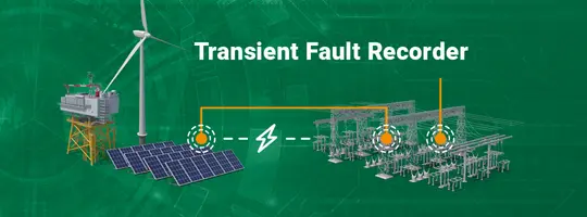
Switchgears essentially have two different communication tasks, which the IEC 61850 standard handles using the station bus and process bus. While the station bus controls the exchange of status information between devices at field level and the control room, the process bus is intended for real-time communication and for exchanging relevant automation-related events. This also includes information for clarifying errors, and the exchange of measured values.
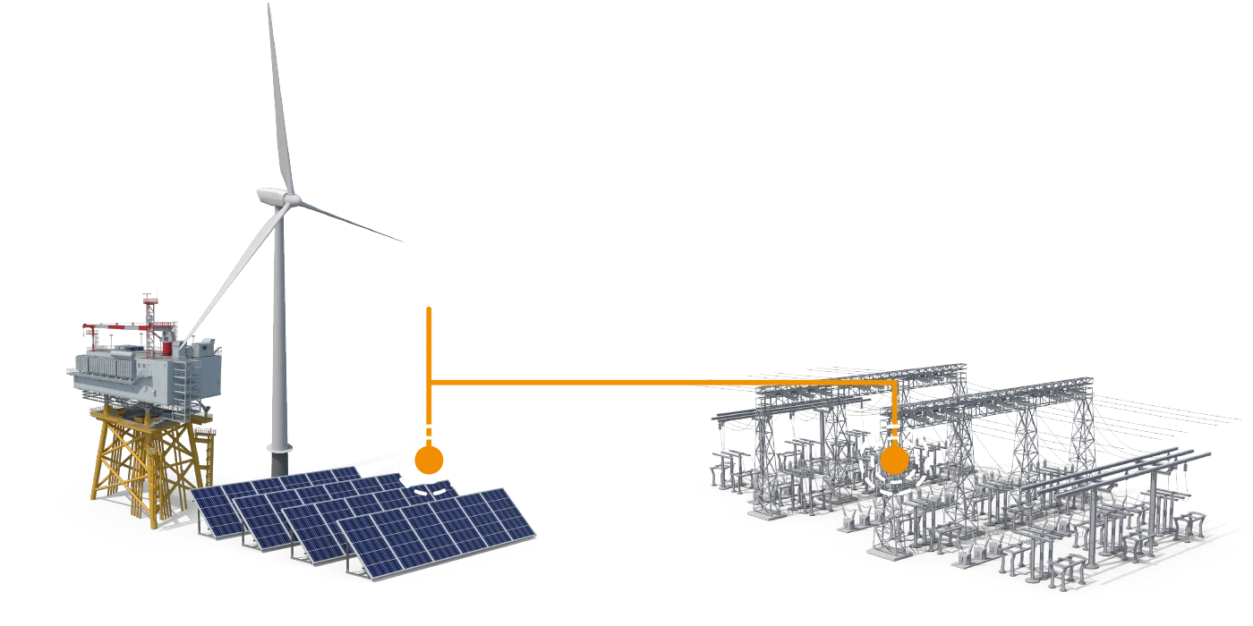

Thanks to its IEC 61850 interfaces, the iba system enables status information to be obtained from the IEC 61850 devices via MMS (Manufacturing Messaging Specification) as an active user in the station bus, and enables the real-time communication of events (GOOSE) and measured values (9-2 SV) to be acquired at process bus level.

Discover how the iba system supports operational excellence and enables visibility for the grids of tomorrow. Meet us at CIGRE in Paris.

MMS communication is a traditional method of client–server communication whereby a device, such as a protection relay, exchanges data with the higherlevel control system. This data may include device variables and parameters as well as measured values and status messages.
With MMS, the IEC 61850 standard offers a separate reporting and data set function which is used with the iba system. ibaPDA registers with an IEC 61850 device (server) for a particular data set as the client and, if the data in the data set changes, receives an update from the IEC 61850 device without the need for further polling. This ultimately boosts performance and minimizes the amount of communication required.
GOOSE communication is used to exchange information between IEC 61850 devices in real time. This communication is based on the publisher–subscriber principle, carried out in real time, and used to transmit safety/security-related and time-critical events. ibaPDA monitors the data exchange in the network as a subscriber and filters out relevant signals together with the time information so that fault events and system responses can be accurately reconstructed.
Sampled Values are used to transmit digitalized measurement variables within the range 4 kHz to 100 kHz, and provide an alternative to the traditional way of acquiring measured values with conversions of analog signals. ibaPDA acts as an additional subscriber in this network and, when an event occurs, also records fault records on the basis of the Sampled Value data. As a result, the measured values that the protection device acquired during a fault can be documented.
The iba system acquires the data together with the time stamp of the devices that sent it – this is the only way to follow events precisely. You obtain valuable insights into how the events developed over time and can appropriately evaluate the system response. In doing so, you obtain answers to a variety of questions: Which protection device was the first to respond to the error? Was the system response coordinated well? The transmission duration is irrelevant here as the events are acquired together with the time stamp of the devices that sent them, which ensures accurate results.
The iba system enables you to see the grid operations in the stations and, in conjunction with iba process monitoring, shows their impact on the connected plants. It also works the other way – you can also see what impact the processes are having on the grid operations, such as when switching large loads on or off.
If communication with the IEC 61850 devices is active, ibaPDA reads out all data points and generates internal address books. You can then quickly find your desired signals there and select them for recording.
Even if communication with the IEC 61850 devices is not active, the address books can still be generated from the engineering files (*.scd, *.cid, etc.). This is required during the configuration stage or if it purely concerns process bus sniffing with read-only access to the network – making it a handy function in ibaPDA.
Protection devices have their own recorder for recording fault records in Comtrade format. ibaPDA recognizes when a protection device has created a record with its own recorder, e.g., following a fault, and copies this record file to a defined target directory. The copied file can be exported to the iba-DAT format or other data formats later on using ibaDatCoordinator and ibaAnalyzer.
The file names can also be supplemented with information like the device name, time stamp, etc. to ensure the files remain matched up with their respective source device, even when many protection devices are involved.
The advantage of the iba system is that you do not need to analyze lots of individual device records – instead, it looks at the overall system in one record. You obtain one central overview of the event messages pertaining to all protection devices and can analyze errors faster and target your response more accurately.
The following functions of the iba system are used in this application.
These leading companies already rely on the iba system.














Download the demo of ibaPDA and ibaAnalyzer and start optimizing your processes today. Try it free of charge for 30 days!
Request a ibaPDA-Demo LicenseSuccessful applications and real solutions with the iba system.
Analyze system faults with precise, high-resolution measurements: Electric systems react extremely quickly to errors. Compensation processes then…
Learn moreIdentify optimization potential with power and process monitoring: Power quality measurements are normalized measurements that qualify the voltage…
Learn more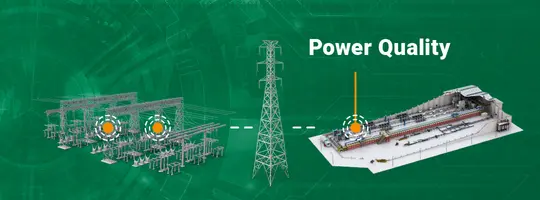
Acquire and analyze energy flows and consumption data: The iba system is ideal for evaluating your energy efficiency as it monitors energy and process…
Learn more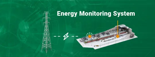
The iba system tells you exactly what is happening in your plants and your energy system. The components are all perfectly coordinated with one…
Learn more